The Grill 
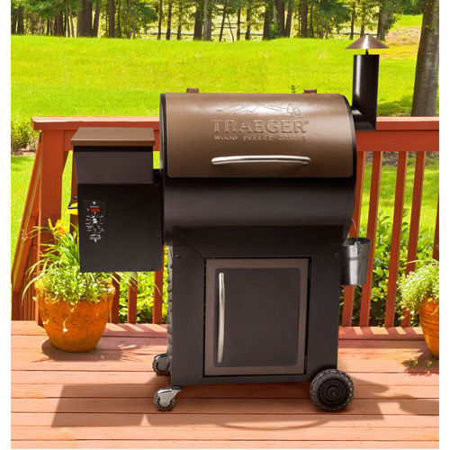
After lusting after a Traeger for some time, the Traeger sales men at Costco had my number. The primary resistance happened to be tagging along, and saw the look on my face that I was going to be walking out the door with a Traeger Junior. Somehow she convinced me to think it over while we shopped. I do have to admit when she is right, and we walked away with the Traeger Century, twice as large as the Junior.
The Traeger is a smoker that burns wood pellets. It is simple to use, almost inspired by the Ronco slogan. A couple of hours at low-and-slow can result in some delicious BBQ.
 The cooking station is a steel cylinder. The meat sits on grill grates, which are suspended above the firebox. Small pellets (think rabbit food) are fed into the firebox by an auger from the pellet storage. During startup, an electric ignition hotrod ignites the pellets. Since this is an exothermic reaction,the firebox fire is self sustaining after ignition. A small fan run continuously to provide oxygen to the firebox, and force the smoke to flow from the bottom of the cylinder out the chimney. Therefore, there are only 3 electronic components, the fan, auger, and igniter. All 3 components run at 120V AC.
The name of the game is low, steady, heat. The temperature of the grill is regulated by augering more pellets in to the firebox. The original Traeger controller had a few settings, that corresponded to particular auger duty cycle (the auger is either on or off). However, there are many factors in play such as outside temperature, wind, and pellet type. Therefore, open-loop control is not very effective. Traeger introduced the "elite" line, which offered digital controllers. By adding a RTD temperature probe to measure the grill temperature, the controller is able to vary the auger duty cycle with the goal of maintaining a set temperature. However, the interface remains simple, with a knob that changes the set temperature. Furthermore, the Traeger digital controller implements simplicit control algorithms, has can easily swing +- 50F.
The Goal
Much like Everest, my new Traeger immediately needed a new controller, because it was there. I was certainly not the first to add an aftermarket controller to Traegers, often with impressive results. Although there were off the shelf solutions, what fun is that? My goals:
- Tighter temperature control (+- 10F)
- Internet control
- Grill and meat temperature plotting
Platform Selection
The controller has to be capable of toggling 3 relays, reading two RTDs, and performing simple calculations. Additionally, I want it to have WiFi capability for backhauling this information. 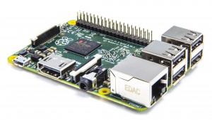
When you start talking about DIY controllers, a microcontroller such as the Arduino always pops to mind. However, perhaps only similar in size and relative cost, the a minicomputer such as the Raspberry Pi is also capable of achieving similar results.
Microcontrollers do one thing, and they do them well. They are typically programmed over serial, and begin execution as soon as they are powered up. Since the program is held in nonvolatile memory, they are good for embedded solutions. They generally run C or C-like code. These can be had for approximately $10, ready to run.
At the other end of the spectrum, are Raspberry Pis. These little devices run an ARM version of linux, and are very capable. While the board itself is $35 (now $5 with Raspberry Pi Zeros!), they require an SD card, power supply, and WiFi adapter. Therefore, the costs can easily exceed the cost of a microcontroller.
Pros of RPi vs. Microcontroller:
- Flexibility - No different than operating a Linux box, but with input and output pins! This allows the programmer to leave the network stack to the OS, and program in any language. I am a big fan of Python. Furthermore, this lets you leverage ANY python module.
- Ease of programming - The RPi can be SSH'd to via Wifi. A microcontroller requires a physical link. This either forces the grill inside (dangerous) or the programmer outside (cold).
- Debugging - The RPi is inherently interactive over an SSH session. Therefore, you can manually read and write to pins and immediately observe the results. With a microcontroller, you would have to setup a debugging framework by writing to the serial port. Although I am ashamed to admit it, I do not own an oscilloscope. However, the pigpio allows you to have a virtual oscilloscope that displays the state of the RPi pins! Very cool, and proved useful.
- Familiarity - Well, that is particular to me
Cons of RPi vs Microcontroller:
- Longer boot time
- Expects graceful shutdown - This is remedied by mounting the SD card read only
- Cost
I am sure this entire discussion is biased, and you have a good sense of what direction I chose. I picked up a Raspberry Pi 2 (the additional cost was minimal compared to a Raspberry Pi 1, with more umph) and the necessary accouterments and was well on my way.
Part List
| Item | Part | Quantity | Price | Subtotal |
|---|---|---|---|---|
| Controller | Raspberry Pi 2 | 1 | $36.99 | $36.99 |
| SD Card | SanDisk 8 GB microSDHC Class 10 | 1 | $8.05 | $8.05 |
| WiFi | 802.11g/n /w Antenna | 1 | $9.99 | $9.99 |
| Case | Clear Case | 1 | $8.79 | $8.79 |
| Power Supply | 20W AC/DC 5V Power Supply | 1 | $11.07 | $11.07 |
| Total | $73.89 |
The Hardware
With the RPi selected, all that was required was to fill in the gap between the Traeger and the RPi, which wasn't too difficult.
Traeger Control (Output)
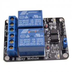 As mentioned earlier, the Traeger has 3 components, the fan, auger, and igniter that run at 120V AC. These components connect to the controller (any controller) with a total of 4, 2-Pin molex connectors (AC + 3 Components). However, the RPi is not capable of switching 120V. Therefore relays would be required. At another level of annoyance, most relays run at 5V to reliably energize the relay coil while the RPi General Purpose Input Output (GPIO) pins operate at 3.3V.
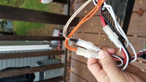
However, a little relay board, similar to one by SainSmart comes through to save the day. It is capable of switching large loads at 120V, can take a 5V power supply and the input pins are simply connected to ground to energize the relay. Fortunately, the RPi has a 5v output (from the power supply) and can be used to trigger the relay. Since each board can switch a pair of relays, two boards were needed.
Part List
| Item | Part | Quantity | Price | Subtotal |
|---|---|---|---|---|
| Relays | SainSmart 4-Channel Relay | 1 | $8.99 | $8.99 |
| Plug | Molex Plug | 4 | $0.27 | $1.08 |
| SSOP Breakout | SSOP20 to Breadboard Breakout | 2 | $5.42 | $10.84 |
| Pins | Molex Pins | 8 | $0.13 | $1.04 |
| Total | $19.68 |
Temperature Reading (Input) 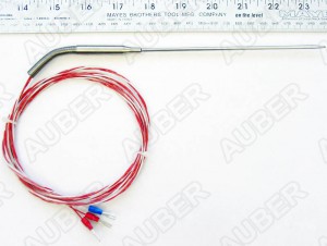
Now that we can control the Traeger components, time to make some informed decisions. I wanted to be able to read the grill and meat temperature. Since the grill already had an RTD temperature probe, I acquired another RTD probe for the meat temperature. An RTD, or Restive Thermometer (D?), consists of a metal (typically platinum) that changes resistance as the temperature changes. The temperature can be determined from the measured resistance. They are commonly Pt100 or Pt1000 with a nominal resistance of 100 or 1000 ohms, respectively. The RTD probe in the traeger is Pt1000 (despite the annoying part number Pt100).
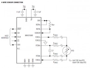 So, you are probably wondering what use an analog RTD is to a RPi living in a digital world. Meet the MAX 31865. This little IC reads RTDs and communicates over SPI, which as you guessed, the RPi speaks. The MAX 31865 comes in a SSOP 20 package, which requires surface mount soldering. Although I had never done it before, it was pretty easy with some solder paste and a heat gun. I connected them to breakout boards that are compatible with the standard 0.1" breadboard spacing.
SPI is a nifty little protocol. It uses 4 wires, Master-Input Slave Output (MISO), Master-Output Slave-Input (MOSI), Clock (CLK), and Chip Select (CS). Multiple SPI devices can be used on the same bus, each with shared wires except CS. CS gets pulled low for the slave the master is talking to. CLK indicates a clock cycle, and the master and slave pull high or low the MOSI or MISO respectively. With this in place, we can write (and read) bytes from registers of the MAX 31865. The datasheet MAX 31865 has excellent documentation, describing configuration and the value of each register.
In the end, I was able to leverage the python SPI library to handle the RPi <-> MAX 31865 communication. I was then able to put together a module that reports the current RTD temperature.
Part List
| Item | Part | Quantity | Price | Subtotal |
|---|---|---|---|---|
| RTD Input | MAX31865 (SSOP20) | 2 | $3.47 | $6.94 |
| Reference Resistor | 1k Ohm Resistor +- 0.1% | 2 | $0.65 | $1.3 |
| Capacitor | 0.1 uF Capacitor | 4 | $0.10 | $0.40 |
| Capacitory | 10 nF Capacitor | 2 | $0.10 | $0.20 |
| Total | $8.84 |
Power
The RPi requires a (quality) 5V input. Typically this is provided over a micro-usb header. Conveniently, the relay boards can be powered from the RPi 5V GPIO pins. However, the Traeger provides us with 120V AC via a molex connector. Rather than add an ugly USB power supply externally, I added a AC/DC 5V 20W power supply to the circuit.
Assembly 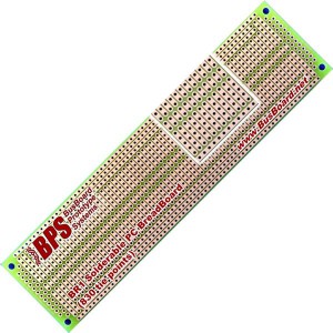
I began prototyping on the standard breadboards with 0.1" hole spacing. However, lose wires are a receipt for disaster. I certainly didn't want to debug a lose connection years down the road. A PCB would have been a great solution, but the effort and cost were not justified. Therefore, I used a solderable breadboard which has the advantage of permanence and transition from the prototype breadboard.
An Adafruit Cobler was used to provide an interface for the RPi. This provides access to all of the GPIO pins via a 40-Pin IDE cable.
Part List
| Item | Part | Quantity | Price | Subtotal |
|---|---|---|---|---|
| Breadboard | Solderable Breadboard | 1 | $6.5 | $6.5 |
| Cobbler | Adafruit Pi Cobbler Plus | 1 | $6.95 | $6.95 |
| Jumpers | DC Connections | |||
| Wire | 18 GA for AC Connections | |||
| Misc | ||||
| Total | $13.45 |
LCD Display
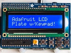 You may wish to add an LCD for direct control from the smoker. I find that I rarely actually use the LCD/button on the device, and primarily use my phone. The Adafruit LCD Kit is a great use, and the PiSmoker software is written to take advantage of it. The LCD connects using the IC2 bus, and requires 5V power. I leave it up to you to implement the waterproof casing and external buttons.
Wiring Diagram
Where's the beef? Well, you aren't getting it. A good wiring diagram would do wonders for repeating this project. However, it would also discourage understanding the logic. Plus, since good wiring diagrams are hard to make, I am going to skip that step. However, the connections that need to be made.
- Traeger AC -> AC/DC Power supply
- Traeger Fan -> Relay Board
- Traeger Auger -> Relay Board
- Traeger Igniter -> Relay Board
- 5V DC Power -> RPi, Relay Boards
- 3.3V DC Power -> MAX 31865s
- SPI: MISO, MOSI, CLK, CS1 & CS 2 -> MAX 31865s
- Resistors and Caps for MAX 31865 (See datasheet)
- RTD -> MAX 31865
- GPIO for Fan, Auger and Igniter -> Relay Boards [Double check with PiSmoker.py]
I suggest you understand the flow of information, study the MAX 31865 datasheet, and make the connections. I realize this is probably unsatisfying, and I'd be happy to post a good wiring diagram if someone else makes it.
Software
Implementation
 A Raspbian based linux distrubution was used on the Raspberry Pi. DietPi was select since it is relatively lightweight, however, I am a bit concerned about the long term maintenance. Therefore, if I were to do it again, I would likely us Raspbian lite. However, the goal was to keep the installation as light-weight as possible, avoding booting a GUI and other unnecessary services. Python was used for the PiSmoker implementation. The required code, and modules is available on GitHub. The script runs as root, primarily due to access control to access the underlying pins.
 The local service reports states (temperatures, on/off toggles, etc) to a great webservice, Firebase. Conversely, the client pushes parameters (hold temperature, mode, etc) to Firebase, which PiSmoker implements. The web clients use a static HTML/JS page that interfaces with the Firebase database. Therefore, PiSmoker does not need to be internet addressable, and the load of serving content is handled by Firebase. I have been extremely impressed by Firebase, and think this is a perfect use.
Modules
The smoker application, known as PiSmoker consists of a few modules that run on the RPi:
- PiSmoker.py - Main loop that handles communication with the Traeger, RTDs, and Firebase.
- Traeger.py - In the spirit of future extension, the toggle of states (fan/auger/igniter) is handled by this library. In this implementation, it toggles relays.
- MAX31865.py - Subprocess that initializes each MAX31865 RTD, and reports the current temperature.
- PID.py - This module provides a fairly straightforward PID implementation. It is initialized with PID parameters, is updated with the current reading, and responds with a new command.
- LCDDisplay.py - Subprocess that displays pertinent information of interest to the operator. Also updates PiSmoker parameters on button push
In my opinion, most of these modules are fairly self-documented. Therefore, I suggest that you read through them and understand what is going on.
PID Controller
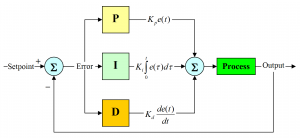 I spent more time thinking about this than I would care to admit. PID controllers are commonly used in industry, and calculate control based on the Error in a Proportional, Integral, and Differential sense. While PID basics are easy to understand, very few implementation examples are provided. What I finally settled on is cobbled together from Wikipedia, Control Texbooks, and the experiences of the fine folks at Pellet Heads.
W have a Process Variable (PV) that we want to control [Grill Temp] to the Set Point (SP) [Target Temp]. We can calculate the Error (E) as the difference of the two:

IF the GrillTemp is at the TargetTemp, no need to make any changes. The controller gains,  are defined by the operator. For a timestep
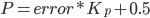
  , the proportional component of the new command can be computed:
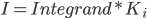
The integral component sums up the error over time:

The derivative component attempts to predict the future position based on the change in error:

The new command,  , can be calculated as the sum of each of the PID components:
A couple of quick thoughts on what this all means in our context. What is the command, ? How can we control the grill temperature? Well, the only thing we can do is turn the auger on and off. Therefore, is defined as the auger duty-cycle. Therefore, it is the proportion of the time the auger is on. A command of  would be constantly running the auger, so maximum temperature. A command of
  would turn the smoker off.
It appears to be more common to use different definitions for the gains, rather than  directly.
- Proportional Band (
 ): This is the temperature band centered around the set point, that the controller is active. If the error is greater than
  , the command is
  . If the error is less than , the command is
 - Integral Time (
 ): Time (in seconds) to eliminate the integral error.
 - Derivative Time (
 ): Time (in seconds) to predict the future value.
These three parameters can be used to calculate the appropriate values.
So, what is that  doing hanging out in the P term? This centers the control at 0.5 if there is no errors. While this is likely not the case, it provides a starting point. The integral term will produce a constant offset to determine the steady-state control signal.
While PID control is (relatively) easy to understand, tuning is not. Therefore, I leverage what other values had been used for Traegers. I stand on the shoulders of giants, and used the recommendations from BMerril on Pellet Heads.
Firebase Authentication
Firebase defaults to allowing all users read and write access. To limit write access to those authorized, add the following to the rules:
{
"rules": {
".read": true,
".write": "auth !== null"
}
}
The PiSmoker and webclient use Firebase tokens for authentication. Firebase provides documentation for generating each token.
Web Client
 The webclient is a static HTML page with several custom JS scripts to provide realtime updating. The client pushes and pulls from Firebase. The webclient is available in the GitHub repository, and can be served from anywhere. In fact, the FireBase static hosting would make the most sense.
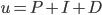
The web client displays the current grill and meat temperature, and their history. It shows the current status of each of the Traeger states (fan/auger/igniter). It allows the operator to set the current mode (temperature hold, smoke, etc) and the appropriate parameters. If desired the operator can queue up commands in a program, with specific targets, such as time or meat temperatures, to advanced to the next mode. In general, it is simplistic, but suites my needs well. It works well on my phone as well.
If the user accesses the URL without an authentication string, they are only able to view your progress. If a "?" and then a firebase authentication token is provided (and verified), they will be able to change the smoker settings. Be careful with this!
What needs changed
For the most part, PiSmoker was written to be as generic as possible. However, every implementation is different. You should be able to get away with changing the following:
- PiSmoker.py - The top 20 lines allow you to set static parameters. This will let you change the RPi pins associated with each relay, etc.
- f = open('/home/pi/PiSmoker/AuthToken.txt','r') will read the Firebase authentication token (required)
- firebase = firebase.FirebaseApplication('https://pismoker.firebaseio.com/') This should be changed to target your Firebase instance
- www/js - These files should be updated to target your firebase instance.
Conclusions
It is a bit of a cobbled together set of tools, but they work together well. The end result is a controller that meets all of my goals. I can control the smoker remotely, and hold the temperature generally +-3F. Furthermore, I enjoy monitoring the process remotely. I love giving my guests the URL, and letting them know to come over when the meat is 165F.
I would certainly love your input. The code is free to use, and I'd love to incorporate any improvements you may think of. I also realize everybody has their unique style, and I am no different. However, if I little community popped up with PiSmokers, I would be more than happy to participate.
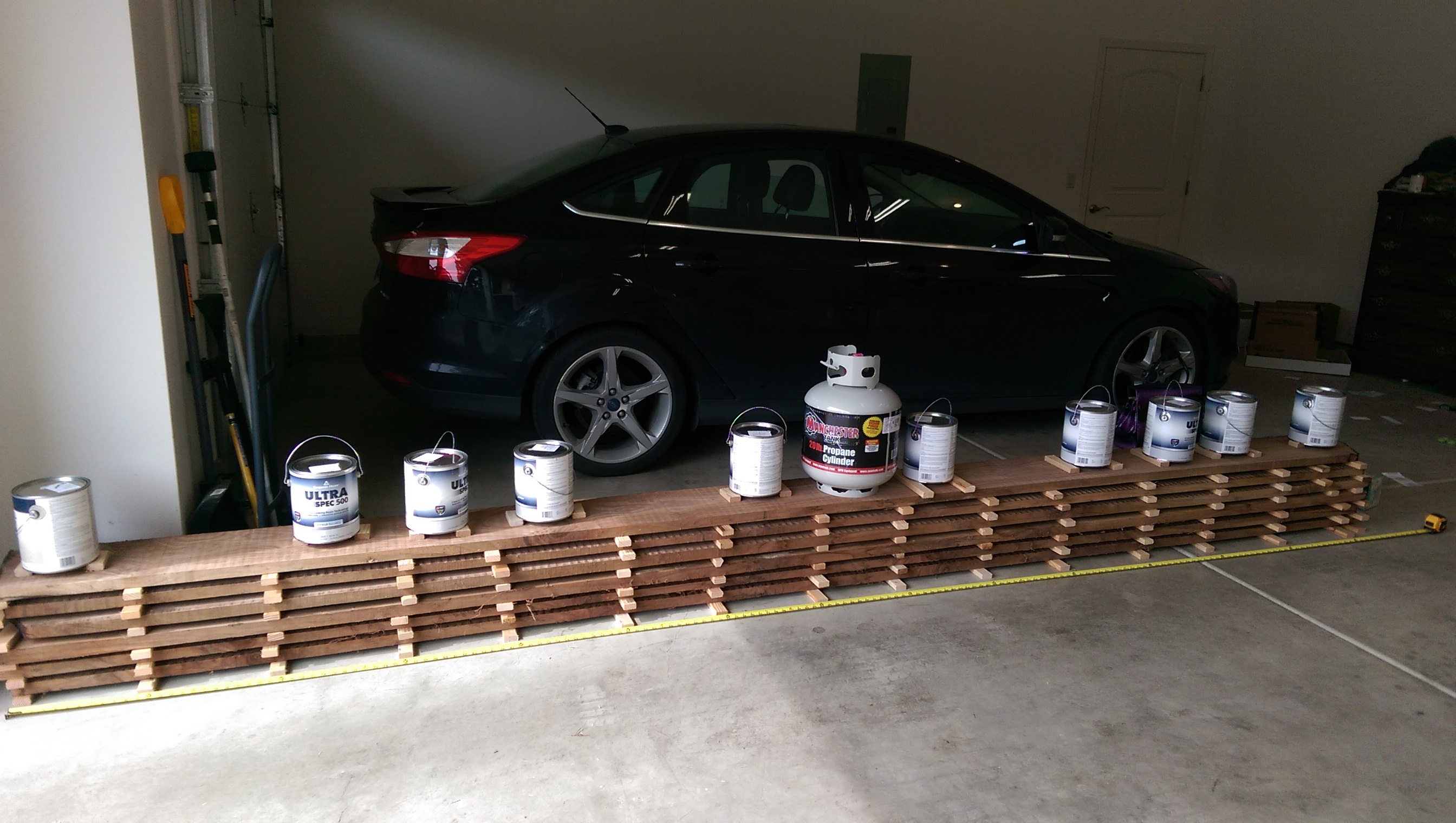
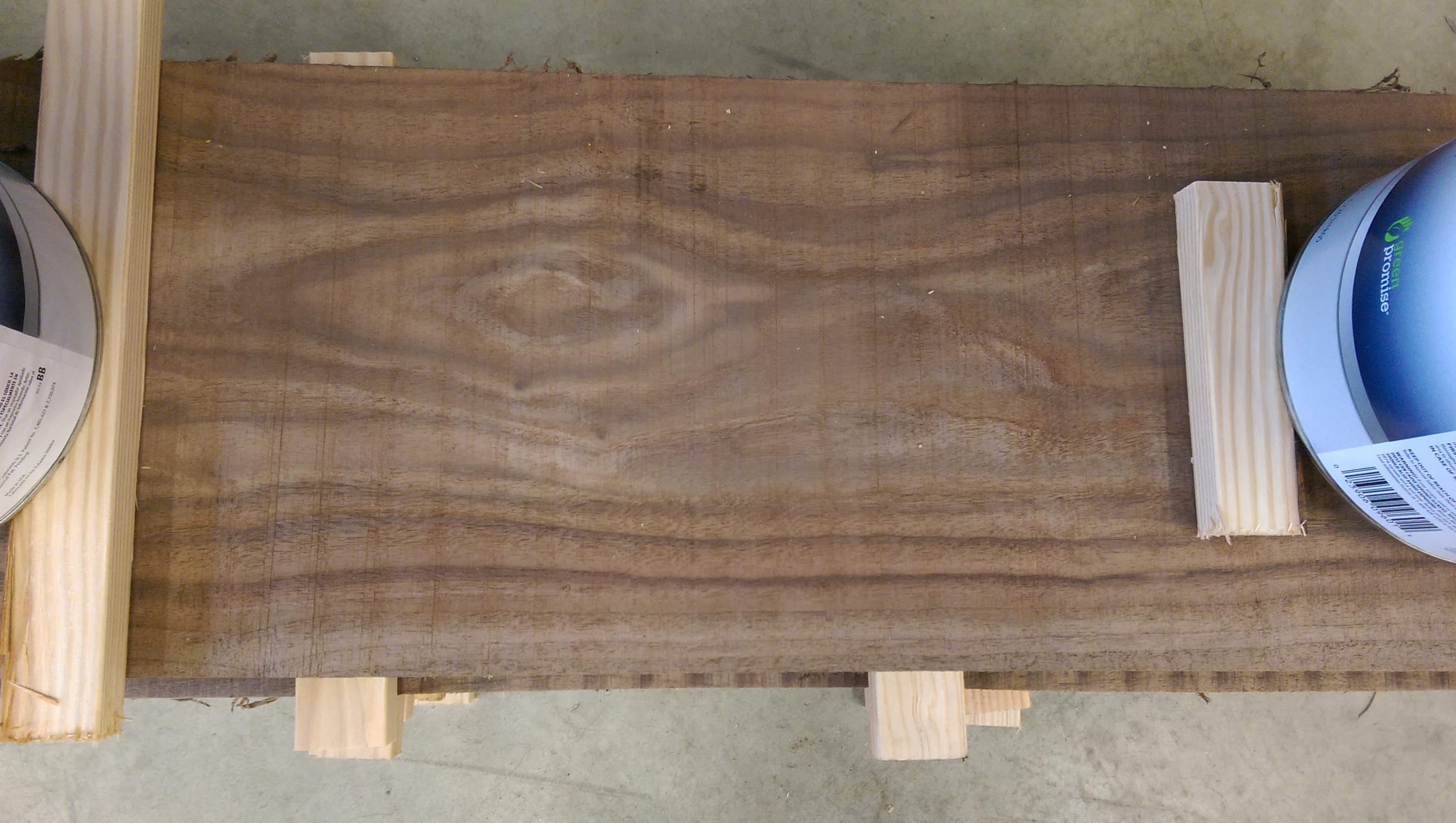


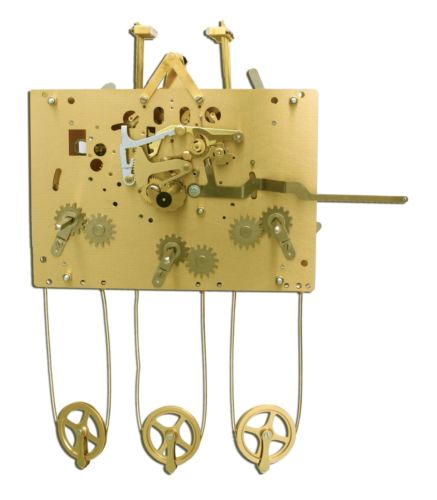
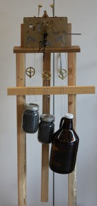 I finally got tired of having a movement, and not having it in action. However, a reasonable case is way to far away, so I put together a test rig. The rig consisted of some 2x4s, and a cedar top plate that allowed the cables for the weights to pass through. I picked up some lead shot (for making shot gun shells) for weight. The left two weights are 7.7 lb mason jars. The right weight is a 9.9 growler. The horizontal bar was required to keep the weights from interfering with the pendulum.